|
Automatic Band Decoder
Introduction
I got over some cheap Liquid Crystal Displays (LCD) and wanted to try to make something with them. I had experimented some with LCDs earlier but wanted to add them in a "real" project. Since I have got a development kit for AVR microcontrollers (ASTK500) it is very easy for me to make applications that can do quite complicated things with very little surrounding electronics, so I decided to build my own Automatic Band Decoder (ABD).
After doing some research of the most popular decoders on the market (as topten, WX0B's and microHam) I chose how my box would work. I wanted to make a box that was not very expensive to manufacture but still functional and of course have a nice appearance. All the ABD I have seen are made for only one radio and since the LCD I was going to use were 16x2 (16 chars, 2 rows) I thought I would make a decoder for both radios in one box. Since I use Kenwood rigs and there is not any output for band data I thought I would use the LPT ports on the computer instead, making it very easy to build small adapters that makes it possible to use with ICOM and maybe Kenwood rigs in the future (see a later project).
The things in this project that might cost a little depending on where you find them are:
Liquid Crystal Display (LCD)
Microcontroller (AT90S8515)
The box
Some things that can be tricky in this project is making the Printed Circuit Board (PCB) and getting the AVR microcontroller programmed. Hopefully you have a programmer yourself or maybe know somebody who has got one.
Design
Inputs
A four pin input for each radio
PTT from each rig
DC Voltage (~13.8V)
Outputs
2x6 output that can sink 500mA
Schematic [Click to see (pdf)]
This band decoder worked really well. Unfortunatly it got toasted in a lightning strike, autumn 2004. Therefor I have not
rebuilt it because I am working on another version. I have tried it though and it worked really fine. I will also
try to find the source code for the AVR controlling it and publish it here on the page later.
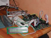
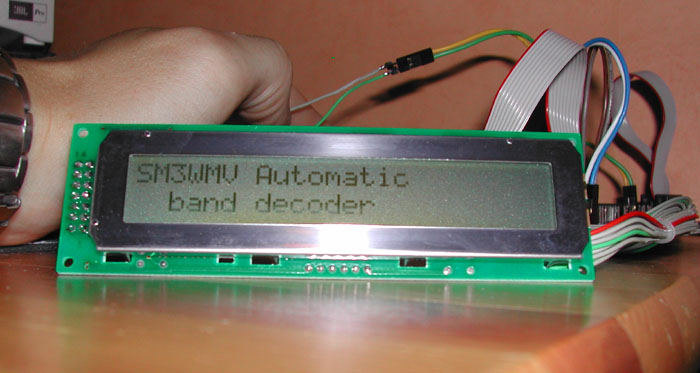
This display is 24x2, the one that was to be used in the project when it was done was a 16x2.

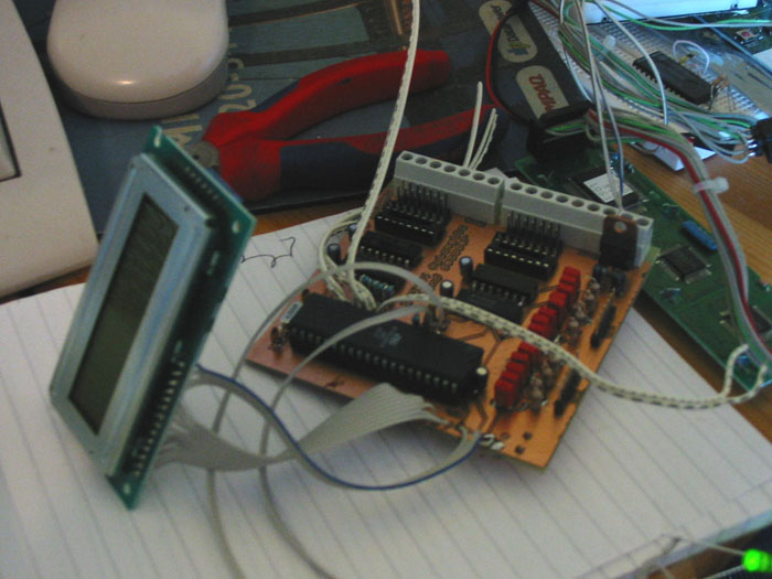
This is a picture of the finished PCB with the 16x2 display connected.
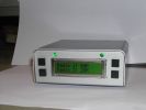
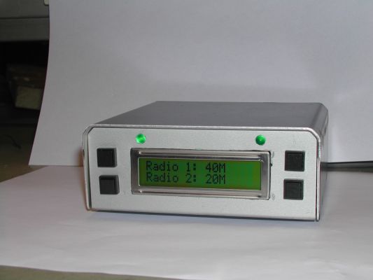
Here is the finished product. I am not pleased with the finish of the box.
|